Aim
To light the LED's on the Digital Signal Processor (DSP)
Apparatus / Setup
1. Connect the Texas Instruments DSP to the PC via Parallel/ USB port. Power the DSP.
2. There are a few tools for checking whether PC to DSP connection has been successfully established. These may be found from the Start Menu.
Start -> Programs -> TI Cxxx (folder where TI DSP executables are stored) ->
3. Once the DSP is connected, start MATLAB. From MATLAB, start Simulink. We shall use Simulink to design our circuits.
4. Configure Simulink / MATLAB to recognize the target DSP. Your lab-instructor may be able to help you in this.
After opening a new file in Simulink, go to the Simulation menu -> Simulation Parameters -> choose Real Time Workshop tab -> in Target Selection area, press Browse -> list of available tabs comes up, select Target for Texas Instruments TMS320C6000 Processor. The Build button should now show Build and Run. See Figure 1.
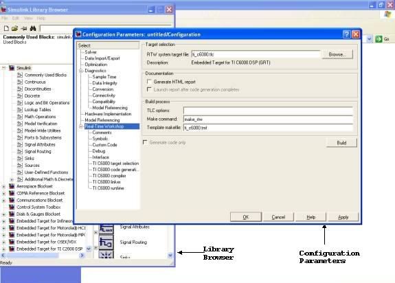
Figure 1. Screenshot of Simulink Configuration Window
Procedure
- Each of the 3 LED-s can be individually switched ON and OFF. Thus we can use a binary coding of 0 to 7 to light the LED-s. For example, an input of 6 (= 4 + 2 + 0) to the DSP should correspond to 2 LED-s ON and 1 LED (corresponding to LSB) OFF.
- To do the same on the DSP, we make the following circuit on Simulink.
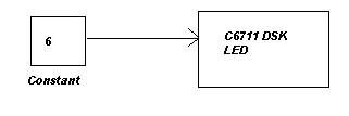
- The circuit is very simple. To get the required blocks, you may have to browse the Simulink Blockset Library. The library is quite large. There is an option of searching blocks by name but that is not very powerful. So I suggest you have a run-through of all the available modules to get a good feel of the power of Simulink.
- Once you have made the circuit and Simulink is properly configured to recognize the target DSP, all you have to do is to again go to the Simulation Parameters menu and press "Build and Run". After that, sit back, relax.... and watch what happens. If all has gone well, you should see a set of glowing LED-s in the end. And MATLAB/Simulink should give the message that the DSP is successfully running.
Discussion
When we were just about learning the ropes of programming, we used to draw flowcharts first. Then we would write the C / BASIC / LOGO code to implement the flowchart. Then we would ask the compiler to convert our ‘High Level Language’ to ‘Low Level Language’. Finally, when the code for our flowchart got executed on the PC, it was all in terms of ‘0’-s and ‘1’-s.
This process from Flowchart to 0/1 takes place so fast that we hardly realise the things going on behind. But while working on the DSP, one can see the step-by-step process taking place. (Although here, the C-code generation is automated!!)
- MATLAB / Simulink checks whether the circuit is correct and then converts it to C-code
- In the background, Code Composer Studio (CCS) starts up and a new project is opened which includes the above mentioned C-code.
- CCS converts the C-code to machine understandable 0/1 format. (There will be differences between the 0/1 executable for different target DSP-s).
- This 0/1 executable then travels via the Parallel / USB port to the DSP, and once over there, starts ‘Running’.
Phew! So much effort for lighting a few LED-s… Seems useless now, doesn’t it? But when complicated DSP algorithms can be implemented and executed on DSP by this same process, the trouble seems worth taking.
Post-Script
While working on C6711, I observed that the LED circuit (using ‘6’ or any number from 0-7) did not work. So I repeated the whole Flowchart to 0/1 process for different numbers and found that a positive bias was required. (I have not been able to figure out the reason yet.) The circuit that worked was

You should try yourself to find out the ‘magic’ bias number.
3 comments:
I'm trying to execute this LED exercise on a TMS320C6713 DSK, but I keep getting error messages. I used the Configuration Parameters shown in the screenshot, but that wasn't enough.
Can someone PLEASE explain ALL of the details needed to properly configure all this so everything works? I know that my DSK kit is connected to my computer, because it passed the diagnostic test.
This is so frustrating. So close, and yet so far.
why dont you leave a mail at my id - kritisen AT gmail DOT com ... please give some more details about your setup
its so easy in C6713.. juz specify ur probs n detail
Post a Comment