Wednesday, February 15, 2006
Saturday, February 04, 2006
Introduction
After taking the opinion of several experts in this field (Professors and working Professionals), we have come to the conclusion that there is serious need to disseminate the expertise gained by
us (me and my batch mates at IIT) on Texas Instrument’s “Digital Signal Processor”.
The importance arises from the fact that there are no experts on this most productive instrument at IIT. In fact we were the first batch to work on this. The steep learning curve one needs to go through, before any significant use of this instrument can be made, makes it desirable for me and my batch mates (Bipul Das, Amlan Ganguly, Koushik Banerjee and others) to share the knowledge we acquired in this area, in course of our BTech thesis preparation last year.
With this aim in mind, I have designed a comprehensive tutorial on the usage of Texas Instruments DSP (Digital Signal Processor). Further, it has been made available online for convenient access at http://dsptute.blogspot.com. This tutorial aims to disseminate the knowledge we, unfortunately, could not directly pass on to our juniors.
We are sure you are with us in our endeavor. Please visit the website and circulate the link to all potential users of Digital Signal Processors. Your feedback is our only source, to understand our drawbacks and make desired improvements. You may send in your comments and suggestions via email or use the “comments section” in the website.
We are looking forward to your kind co-operation. Our mission is to set a trend, which in future will benefit a large section of the student body.
Thanking You
Regards
Kriti Sen Sharma
Saturday, January 14, 2006
1 - Setup & Lighting the LED's (Illumination)
Aim
To light the LED's on the Digital Signal Processor (DSP)
Apparatus / Setup
1. Connect the Texas Instruments DSP to the PC via Parallel/ USB port. Power the DSP.
2. There are a few tools for checking whether PC to DSP connection has been successfully established. These may be found from the Start Menu.
Start -> Programs -> TI Cxxx (folder where TI DSP executables are stored) ->
3. Once the DSP is connected, start MATLAB. From MATLAB, start Simulink. We shall use Simulink to design our circuits.
4. Configure Simulink / MATLAB to recognize the target DSP. Your lab-instructor may be able to help you in this.
After opening a new file in Simulink, go to the Simulation menu -> Simulation Parameters -> choose Real Time Workshop tab -> in Target Selection area, press Browse -> list of available tabs comes up, select Target for Texas Instruments TMS320C6000 Processor. The Build button should now show Build and Run. See Figure 1.
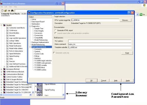
Figure 1. Screenshot of Simulink Configuration Window
Procedure
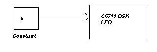
- Each of the 3 LED-s can be individually switched ON and OFF. Thus we can use a binary coding of 0 to 7 to light the LED-s. For example, an input of 6 (= 4 + 2 + 0) to the DSP should correspond to 2 LED-s ON and 1 LED (corresponding to LSB) OFF.
- To do the same on the DSP, we make the following circuit on Simulink.
- The circuit is very simple. To get the required blocks, you may have to browse the Simulink Blockset Library. The library is quite large. There is an option of searching blocks by name but that is not very powerful. So I suggest you have a run-through of all the available modules to get a good feel of the power of Simulink.
- Once you have made the circuit and Simulink is properly configured to recognize the target DSP, all you have to do is to again go to the Simulation Parameters menu and press "Build and Run". After that, sit back, relax.... and watch what happens. If all has gone well, you should see a set of glowing LED-s in the end. And MATLAB/Simulink should give the message that the DSP is successfully running.
Discussion
When we were just about learning the ropes of programming, we used to draw flowcharts first. Then we would write the C / BASIC / LOGO code to implement the flowchart. Then we would ask the compiler to convert our ‘High Level Language’ to ‘Low Level Language’. Finally, when the code for our flowchart got executed on the PC, it was all in terms of ‘0’-s and ‘1’-s.
This process from Flowchart to 0/1 takes place so fast that we hardly realise the things going on behind. But while working on the DSP, one can see the step-by-step process taking place. (Although here, the C-code generation is automated!!)
- MATLAB / Simulink checks whether the circuit is correct and then converts it to C-code
- In the background, Code Composer Studio (CCS) starts up and a new project is opened which includes the above mentioned C-code.
- CCS converts the C-code to machine understandable 0/1 format. (There will be differences between the 0/1 executable for different target DSP-s).
- This 0/1 executable then travels via the Parallel / USB port to the DSP, and once over there, starts ‘Running’.
Phew! So much effort for lighting a few LED-s… Seems useless now, doesn’t it? But when complicated DSP algorithms can be implemented and executed on DSP by this same process, the trouble seems worth taking.
Post-Script
While working on C6711, I observed that the LED circuit (using ‘6’ or any number from 0-7) did not work. So I repeated the whole Flowchart to 0/1 process for different numbers and found that a positive bias was required. (I have not been able to figure out the reason yet.) The circuit that worked was

You should try yourself to find out the ‘magic’ bias number.
Friday, January 06, 2006
2 - RTDX – Real Time Data eXchange (Yahoo Chat)
Aim
To configure and use RTDX – Real Time Data eXchange (Yahoo Chat).
Theory
Compared to PC’s, Digital Signal Processors (DSP’s) are super-efficient when it comes to executing Signal Processing algorithms. Thus they are of immense use in the industry. But when it comes to the simple but essential task of display, the good old PC is miles ahead.
For example, you may run a complex algorithm and get a numerical result, ten times faster on the DSP than the PC. However, you cannot see the calculated value, as the DSP does not provide us any sort of Visual Display Unit (monitor, in simpler terms).
But wait! There is still hope. Texas Instruments DSP provides a mechanism called RTDX which can throw some light (literally!) on this problem. By this method, data is exchanged between the PC and DSP. A two way communication channel is set up. Using that, the result of any complex algorithm as calculated by the ‘super-fast’ but ‘visually disabled’ DSP can be sent to the ‘slow’ but ‘visually able’ PC. This experiment shows just how to do that.
Apparatus / Setup
Texas Instruments DSP – MATLAB & Simulink – Custom application for RTDX (e.g. – “General Purpose Display” provided by T.I.).
Procedure
1. Circuit
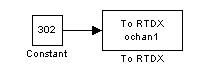
We make a simple circuit as shown below. The expected output is the constant 302, but we intend to generate it on the DSP and receive it on the PC screen. Set parameter ‘ochan1’ within the ‘To RTDX’ box.
2. Setup from MATLAB
Build the above circuit from MATLAB Simulink. (Note that you should choose the option ‘Build’ and NOT ‘Build & Run’ from the Simulation Parameters box. This can be accessed by the following steps.
After opening a new file in Simulink, go to the Simulation menu -> Simulation Parameters -> choose Real Time Workshop tab -> in Target Selection area, press Browse -> list of available tabs comes up, select Target for Texas Instruments TMS320C6000 Processor. The Build button should now show Build and Run. (Same procedure as Experiment 1).
Then, within the Category drop-down menu, choose “TI C6000 Runtime”-> then choose the Build Action : Build. The Build and Run button should again show Build.
3. Setup from CCS
During the Build process, Code Composer Studio (CCS) opens up. A new project is created and the executable for the above circuit is made. However it is still not loaded and remains on the PC awaiting further instructions.
RTDX has to be enabled next. This has to be done from CCS. Follow following steps to do so.
- From CCS, go to Tools Menu -> RTDX -> Configuration control
- Current Settings window opens up
- Uncheck the Enable RTDX checkbox
- Press the Configure button
- RTDX Configuration Control Window pops up
- Choose RTDX mode : continuous mode
- Press OK
- Check the Enable RTDX checkbox
This slideshow illustrates the above process. Zoom in and locate the mouse within these screenshots to view the changes.
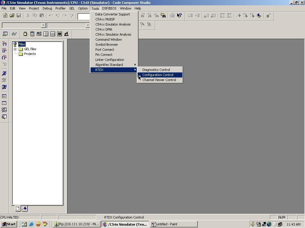 Step 1 | 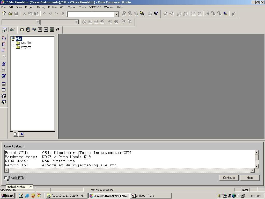 Step 2 |
 Step 3 | 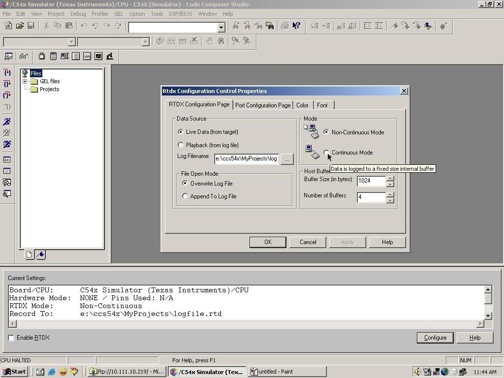 Step 4 |
After enabling RTDX, load the executable onto the DSP from CCS. From File menu -> choose Load Program. Do not execute it yet.
4. External Application Required
At this point, if you run the program on DSP, the value 302 will be generated on DSP and sent to the PC via parallel/ USB port. However we need an application to read the buffer where these sent values are stored. TI provides one such tool – General Purpose Display (GPD). (Search for this app within the folder where CCS is installed on your comp). Within GPD, Select Add Channel and provide the same channel name (ochan1).
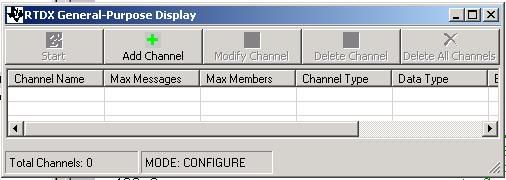
Fig. General Purpose Display Program
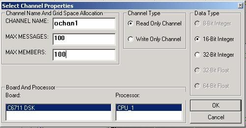
Fig. Options for Adding Channel
Then run the executable on DSP. Just after that, press the Start button on GPD. You should see some familiar values popping up on screen.
Discussion
Provided everything ran successfully before, you can try other variations of the previous program.
For example, you may log the values of the DSP's digital clock using RTDX like in Fig. below.

Thursday, January 05, 2006
3 - Finding an Unknown Frequency (The Number Game)
Aim
To find the frequency of a signal.
Apparatus / Setup
There are 2 parts to this experiment.
- Part 1 : Setting up the circuit and executing the algorithm on DSP. Setup same as Experiment 1.
- Part 2 : Exchanging values between DSP and PC. Setup same as Experiment 2.
Theory
Remember the game in which you asked your friend to think of of any number between 1 and 100? Then you would ask him a few questions relating to the number. After a few such questions, you would tell him his secret number. And he would say, “Yes, that was the number I had thought of. But how did you know?”
Well now we can are going to do a similar thing using our DSP board. Ask your friend to tune the Signal generator to generate a sine wave of any frequency between 500 and 1000 Hz. Then, feed this signal of unknown frequency into the DSP through its' Audio In port. Execute your algorithm on the DSP board. Then ask your friend to check whether a number popping up on your PC’s monitor is the same as his secret frequency. He will be quite amazed when the numbers match his secret frequency!!
There are quite a few ways to find the time-period / frequency of an unknown signal. We shall show the DSP implementation of one such technique.
Suppose we have kept our guessing range within 500 to 1000 Hz. This would correspond to a range in time-period (1/fs) of (1/1000 = ) 1 msec to ( 1/500 = ) 2 msec. Since DSK 6711 supports a sampling frequency of 8000 Hz, the range in time-period would correspond to: -
- 1 msec corresponds to ( 8000/1000 * 1 ) = 8 samples
- 2 msec corresponds to ( 8000/1000 * 2) = 16 samples
Now, Auto-correlation function (ACF) gives values of the correlation at different values of lag (τ). So if we have a signal of unknown frequency, and we find that its’ ACF plot looks like Figure below, we can make a safe venture on the value of the unknown frequency.
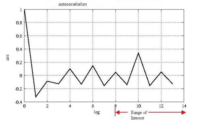
Figure 1 : Plot of Auto-Correlation Function
In the above diagram, the maxima within our range of interest lies at 10 samples. If you do some mental maths, you can quickly say what the value of the unknown frequency was.
Procedure
Part 1 - Circuit
This process of guessing the unknown time-period / frequency by using the signal’s ACF is exactly what we would like to do using the DSP. I will draw below the basic block diagram of a Simulink circuit for achieving the same.
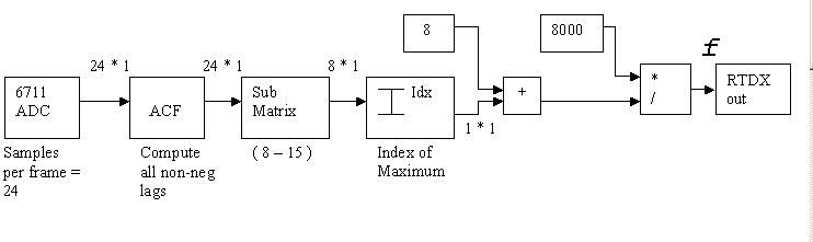
Note that the Sub-Matrix block is required to override the presence of a maxima at lag = 0. The maxima within the range of 8 to 16 samples is what interests us the most.
Part 2 - RTDX
By the above process, the value of the unknown frequency is calculated. The value remains calculated and sits pretty within the DSP. However, as the DSP does not have a monitor/output screen, we have no way of accessing the calculated value!
Unless of course we use RTDX (Real Time Data Exchange). RTDX, as shown in Experiment 2, allows the PC and the DSP to exchange values/data. And as our good-old PC is equipped with a monitor, we can easily see the values calculated on the DSP popping up on the PC screen via RTDX. Follow the procedure enumerated in Experiment 2 to do the same.
Discussion
- You can try out different dynamic ranges (other than 500 – 1000 Hz) to check the performance of the DSP and your algorithm.
- There are other methods apart from ACF to find an unknown frequency. Does FFT ring a bell here?
Wednesday, January 04, 2006
Acknowledgements
- Dr. Gautam Saha (IIT Kgp)
- Snigdhamadhab Ghosh (DSP Lab, IIT Kgp)
- Samit Ari (Research Scholar, IIT Kgp)
- Jithun Nair, Deepraj Sahni and Arka Majumdar (Dept of E&ECE, IIT Kgp)
- Atul Narain (MS Student, University of Berkeley)